Three Easy Steps, Please, Right?
The Truth About Endodontics
The truth is endo is not that easy. The purpose of reviewing this case is to help you understand how I approach cases, how we think about cases, and how we plan for these cases to be as predictable as possible.
To watch the video, click here, or read the steps I took to complete this case below.
Receded Pulp Chamber in Maxillary Central Incisor Steps:
Steps:
- Anesthesia Testing and Patient Acclimation 5:02
- Treatment Planning 6:26
- Target Vertical Depth & Working Length 9:08
- Cementoenamel Junction (CEJ) 12:15
- Level One Field Control: Rubber Dam Isolation 13:54
- Level Two Field Control 15:25
- Endodontic Access 16:56
- Accessing Free Space & Reading the File 22:00
- Orifice Modification 23:49
- Advance to Estimated Working Length 25:46
- Determine True Working Length 28:26
- Guide Path Development 31:28
- Final Shape 34:00
- Final Irrigation Protocol: Mechanical Agitation 34:37
- Canal Drying: Syringe and Paper Point Techniques 38:14
- Initial Sealer Placement 41:01
- Cone Fitting 42:35
- Cone Melting 46:42
- Close the Chamber and Close the Access 50:17
When I present cases like this, we'll focus on the actual technical aspect of the root canal treatment. I've discussed the prognosis with the patient, ensuring they understand the risks and are willing to proceed with the treatment. Also, I assume we've got the patient numb, with a basic understanding of local anesthesia techniques—just infiltrations and blocks, nothing fancy like Gow-Gates or Akinosi. These advanced injection techniques are rarely used in "everyday" practice.
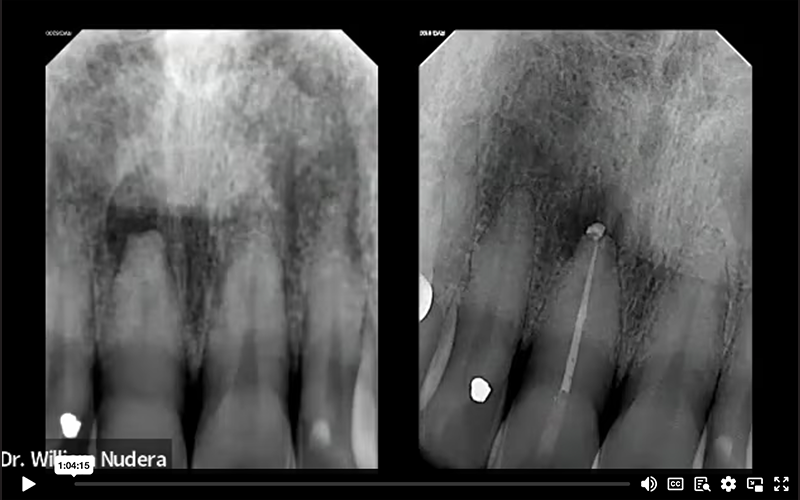
After getting the patient into the operatory and numbing them, the first thing I do is go back to my office and start treatment planning. The periapical radiograph we're looking at shows a few important things. Glancing at the right central incisor compared to the left central incisor, we can compare the radiograph and examine the pulp chamber. The tooth we're treating here is extremely calcified and challenging. While I don't expect students or dentists just learning endodontics to tackle a case like this, discussing it has value in understanding the protocols and challenges.
It's crucial to note that my protocols for a case like this aren't any different than if the canal were wide open. We observe heavy calcifications in the pulp chamber and constriction in the root canal system compared to its contralateral tooth. There's an area of pathology localized to the root apex. Another observation is the actual root itself— the tip of the root. The neighboring tooth has a normal conical root form, but the one we're treating is flat and shorter than its neighbor due to apical resorption.
Anesthesia Testing and Patient Acclimation 5:02
Anesthesia testing serves two distinct purposes. First, as most would assume, we ensure that the applied anesthetic is functioning as expected, confirming the absence of pain sensations. But, in my opinion, the real value of anesthetic testing lies in its secondary benefit, patient acclimation— because anticipation and fear of the unknown breeds anxiety. Strategic anesthetic testing will help shed some light on the unknown as it begins to separate the sensations of pressure from pain.
We first test to ensure that the gingival tissue is numb by applying a little pressure with a periodontal probe around the tooth. Gradually, I increase the pressure. The increase in pressure acclimates the patient, making them aware that pressure sensations differ from those of pain. Then, I perform percussion testing with the same purposes in mind. I gently tap using the back of a mouth mirror, followed by more firm tapping. Acclimating the patient to these sensations fosters their comfort level and decreases anxiety by making the unknown known. I aim to instill confidence and trust, thus creating a smoother experience as we proceed with the treatment.
Treatment Planning 6:26
Once we confirm that the tooth is anesthetized, we further plan for the endodontic treatment. We continue this process by examining the periapical radiograph, again noting the calcified root and the apical resorption. Another vital piece of information contributing to our treatment planning is the cone beam scan. I consistently obtain a pre-operative cone beam scan for all my treatment patients, because understanding the three-dimensional aspects is paramount.
As observed at the 6:47 minute mark in the recording...
To interpret the scan effectively, I align the image along the long axis of the tooth. In this case, we're evaluating tooth number 8 (the maxillary right central incisor). The scan affirms the calcified nature of the situation. Manipulating the scan linearly and rotationally, I align it in all three planes. If you have a scanner in your office and aren't utilizing it for root canal treatments, you should. It's a valuable resource for gathering comprehensive information, and it eliminates most of the guesswork.
With the scan aligned, the anatomy becomes much easier to interpret. In the sagittal view, we observe the facial and palatal aspects; we can clearly identify the lesion. Note a discontinuity in the cortical plate and the flat, resorbed root. Typically, the canal is more visible on the scan than in the periapical radiograph. Transitioning to the coronal view, we essentially confirm what was observed in the periapical radiograph—specifically, the flat nature of the root end. In cases of apical resorption, the apical foramen, as we know it, is no longer present. This defect can create a loss of resistance form and suggest a larger apical portal of exit.
This foresight leads me to contemplate my shaping and obturation considerations early in the process. Understanding that the apical anatomy is altered, effective containment of the obturation material within the confines of the root canal system could pose a challenge if not recognized. This proactive thinking enhances the overall planning and execution of the root canal treatment.
Target Vertical Depth & Working Length 9:08
In our treatment planning phase, we determine a crucial parameter known as the target vertical depth even before touching any instruments or the tooth itself.
This measurement is defined as the distance from the occlusal surface, or incisal edge in this case, to the level of the pulp chamber. Capturing this measurement is immensely valuable, and while attempting to do so on a traditional periapical radiograph is feasible, it's far more accurate when derived from the cone beam scan.
Using my measurement tool, I initiate the measurement from the incisal edge, measuring until I discern the beginning of the canal. It's a meticulous process, ensuring precision. Confirming this measurement involves cross-referencing with another view, in this case, the coronal view. Once again, measuring from the incisal edge until the anticipated start of the canal, we arrive at a depth of 12 millimeters. This reveals a substantial depth of access.
As observed at the 9:58 -minute mark in the recording
A target vertical depth of this magnitude requires a nuanced approach. Dealing with accesses of this depth demands experience and caution. Case selection becomes pivotal, emphasizing the need for practitioners with more experience to handle such situations. For those new to this, especially students, attempting a case with such depth may be challenging. However, for our learning purposes today, it serves as an instructive example, shedding light on the intricacies involved in planning and executing root canal treatments with deep access requirements.
The next step is to determine our estimated working length. Starting from the incisal edge, I measure up to the apex, revealing that the tooth is approximately 21mm long. This estimate is confirmed by examining the sagittal view, again aligning the incisal edge with the radiographic apex, yielding consistent measurements of 21mm.
We now possess one measurement indicating where the canal should be visible and another providing insight into the overall length of the tooth. Armed with these two measurements, a target vertical depth, and an estimated working length, I now have a clear vision of where I should expect to see the canal and where I want the final shape and obturation material to terminate. Acknowledging the presence of apical resorption and anticipating a slightly more open apical foramen due to the necrotic nature of the tooth adds further nuance to the planning process. All this information is crucial before commencing the actual procedure— much of this planning can be done in the time it takes for the patient to become numb.
Cementoenamel Junction (CEJ) 12:15
Returning to the treatment, I plan my access approach. Using a periodontal probe, I align it along the long axis, gently exploring the cervical gingival area to locate the Cementoenamel Junction (CEJ).
As observed at the 13:05-minute mark in the recording
The CEJ is a pivotal landmark, and understanding its position is paramount. An informative publication in the Journal of Endodontics from 2004 discusses the anatomic laws of endodontic access. This publication emphasizes the CEJ's significance in determining the pulp chamber's position. The laws of centrality, concentricity, and the CEJ underscore the importance of this landmark. For those interested, the Journal of Endodontics article "Anatomy of the Pulp-Chamber Floor," published in 2004, is a valuable resource to explore deeper into these concepts, providing insights into achieving well-centered access. If you have access to the journal, I recommend reading it for a comprehensive understanding of these principles. If not, consider reaching out to your local endodontist or exploring options to obtain the article for a more in-depth understanding of these anatomical considerations.
Level One Field Control: Rubber Dam Isolation 13:54
With our comprehensive plan in place, we're ready to proceed. The initial step involves rubber dam isolation to maintain an aseptic field throughout the procedure. Rubber dam isolation is considered a level-one field control protocol mandatory for all endodontic treatments. While there is an exception to delay the placement of the rubber dam to maintain orientation during access, rubber dam isolation techniques are available to make predictable accesses with the rubber dam in place.
I use a number 9 rubber dam retainer for maxillary incisors, and my approach when applying the rubber dam with this retainer is a bit different. I first place the rubber dam retainer on the tooth. Then, I work the rubber dam sheet around the retainer once it is in place. This method requires a large opening on the rubber dam sheet, large enough to stretch over this bulkier retainer design. This method provides better visualization and is more predictable than attempting to work through a small hole punched in the rubber. In cases where a larger rubber dam opening is needed, I take advantage of a split dam technique, creating a sizable opening to stretch the rubber dam over the large number 9 retainer.
After securing and stabilizing the rubber dam, a bite rest is placed on the contralateral side. The bite support helps eliminate spontaneous mouth closing and excessive muscle fatigue.
Level Two Field Control 15:25
Once the rubber dam is securely placed, saliva control must be addressed using our level two field control technique. For this purpose, rubber dam block-out material, such as OraSeal from Ultradent, can be utilized. This product comes in two forms— caulking and putty, with caulking slightly thicker and putty more manageable, in my opinion. Both serve the same purpose, and the application is facilitated using a luer lock White Mac Tip (also available from Ultradent). This product is applied around the tooth to shore up the large rubber dam gaps, preventing saliva from entering the field. This additional step also stops the leakage of our irrigation solutions from the field into the patient's mouth.
Endodontic Access 16:56
Now that level one and level two field control measures have been established, we're ready to proceed with the endodontic access. For a highly calcified case like this, my access will be closer to the incisal edge to maximize straight-line access to the canal. I use a 557 surgical length crosscut fissure bur for this purpose, providing precise dimensions with 4mm cutting flutes and a total length of 7mm to the parallel shank. This bur acts as my depth gauge, ensuring that, by the time I reach the parallel mark, I'm already 7mm deep.
Understanding the importance of this choice requires a brief revisit of our cone beam scan. The strategy of starting the access close to the incisal edge is distinct from the traditional approach, especially when dealing with a calcified case. It allows for a more direct path to the canal, avoiding the challenges of redirecting through a small opening, which is often the case in anterior teeth. The goal is to angle the bur down the long axis for a smoother entry into the pulp chamber.
As I proceed with the access, I'm cautious and deliberate, measuring the depth of my access to ensure I stay on target. There's no rush in a challenging case like this, where the target vertical depth is 12mm. I progress in increments, checking the orientation and ensuring I'm comfortable before advancing. Understanding the dimensions of my bur aids in reaching the desired depth safely.
Considering my target depth is 12mm, I proceed cautiously, incrementally advancing a couple of millimeters at a time and ensuring the correct orientation before progressing. Upon reaching the 12mm target vertical depth, I carefully inspect for internal visual cues. In this challenging case, I may not easily spot the canal. If it's not visible, my approach is not to drill deeper but to pause and conduct a mid-treatment cone beam scan. However, in this case, after drying the access with paper points, I do see a very faint color change in the canal. This color change indicates the presence of the pulp canal space.
The pulp canal space typically appears darker than its surrounding dentinal walls. Therefore, a subtle color change becomes a valuable clue. With this cue, I proceed cautiously, ensuring I'm not advancing deeper than necessary. Again, when in doubt, a mid-treatment cone beam scan can be performed if confirmation is needed.
Accessing Free Space & Reading the File (23:30-minute mark in the recording) 22:03
Once the canal is located, the next step involves accessing the canal's "free space" and "reading the file .” This step helps me understand case difficulty. Free space is defined as the amount of canal space easily accessible to our size 10 hand file; the amount of canal space nature has given us for free— we don't have to work for it. Using the estimated working length of 21mm (obtained from the cone beam scan) and in a watch-winding motion, I carefully navigate through the more constricted root canal system with a size 10 hand file– prioritizing the feeling of the file's movement and sensations rather than applying excessive pressure. Ideally, the size 10 file will reach the estimated working length smoothly and unobstructed, signifying a more routine case.
I don't quite reach my estimated working length, I achieved substantial progress, measuring approximately 18mm of free space.
Orifice Modification 23:49
The next step is orifice modification. As a prerequisite for this step, I ensure that the hand file can reach at least 3mm below the CEJ. Using dedicated orifice openers, such as the ProTaper SX, Vortex Orifice Opener, Brasseler 16mm 20/.08, or Edge SX, I run the motor at approximately 300 RPM to slightly enlarge the orifice. This early removal of coronal interferences reduces friction during subsequent file advancements and promotes a more accurate working length.
For those using a specific manufacturer's file system, look for an orifice opener. It would appear early on in the recommended file sequence. It's typically a shorter file (somewhere between 16 and 19mm) with a small tip size (approximately ISO 19 to 20 or smaller). These dedicated orifice openers feature slightly larger tapers designed to eliminate coronal interferences.
The newest player in the orifice opener category, the MiniKUT MB2 (Blackjack) from Plan B Dental, is available in 17mm and stands out due to its smaller tip size— ISO 15. The smaller tip size may prove more beneficial for more challenging and constricted canals. While I haven't personally used it, colleagues have praised its efficacy; it's an alternative worth exploring.
Advance to Estimated Working Length 25:46
Eliminating the coronal interferences via orifice modification is designed to allow further advancement of our small hand file— ideally to the estimated working length. The file is gradually advanced apically using a size 10 hand file measured to the estimated working length (21mm). In this instance, I applied a bit of watch winding action, and the file smoothly reached my estimated working length.
While this scenario represents an ideal progression, it's crucial to acknowledge that, at times, the file may not advance as expected. This challenge underscores one of the complexities of root canal treatment— the inability to navigate the size 10 file to the estimated working length. When it doesn't proceed smoothly, understanding the available troubleshooting protocols becomes paramount.
Determine True Working Length 28:26
Once the estimated working length is reached, it's time to determine the true working length. The true working length is defined as the actual length of the root canal system from the incisal edge reference point to where the tip of the file reaches the apical foramen. True working length can be determined radiographically, but establishing the length using an electronic apex locator is more accurate (and more efficient). So, let's simplify our understanding of working length and how it relates to our electronic apex locator.
When the apex locator display (and tone) does not indicate that we've reached the "zero" (" apex") mark, it indicates that we are short. Conversely, we're long if the reading surpasses the "zero" mark, triggering the alarm. In my perspective, the optimal measurement is illustrated on the right side of the screen. Here, we achieve a flush position with the "zero" mark, accompanied by a full tone from the electronic apex locator. This position is what I consider the "Electronic Apex Locator Zero" (EAL 0) mark— or simply, "0". Conceptually, I envision the file positioned at the tip of the root apex, perfectly flush with the periapical tissues.
Electronic apex locators work best in a dry environment. Therefore, the initial step in determining an accurate working length is to ensure the removal of bulk fluid from the chamber and the root canal system. Then, using a size 10 hand file, gradually advance the file until the electronic apex locator displays the flush mark ("0" mark) with a single solid tone. Once this position is achieved, measure and document the file length.
In this case, the electronic apex locator measurement read 21mm. Therefore, 21mm is the true working length, and this measurement can be used to determine the extent of the file shape and level at which I want the obturation material to terminate, especially considering the impact of resorption on the apical foramen.
With the true working length (or "0" reading) indicating 21mm (aligning with the cone beam findings), I want my final shape to end 1mm shy of this mark, so I communicate a "shaping length" of 20mm to my team member, and it is documented. This adjusted value also becomes my obturation length. I refer to this length as EAL (Electronic Apex Locator) -1 or simply "-1".
Guide Path Development 31:28
After establishing the true working length ("0") and shaping length ("-1"), the next step involves preparing the root canal system to accommodate larger engine-driven instruments. This process begins by developing a guide path. Similar to using a dedicated file for orifice modification, I recommend utilizing a file specifically dedicated to creating a guide path. Again, if you are using a specific manufacturer's file sequence, and depending on the system, a dedicated guide path file may already be incorporated into the protocol. Look for slender files with small ISO tip sizes. They may come as a single file or could be multiple files. My personal preference is a 17/.04 file, and this is not brand specific. I advise establishing a guide path file to the true working length ("0") measurement— in this case, 21mm.
The case is poised for success once the guide path extends seamlessly from the incisal edge to the apical terminus. Regardless of the initial calcification, a smooth and reproducible guide path signifies an open and accessible canal.
Final shape 34:00
With a smooth and reproducible guide path in place, a predictable final shape can be created. Establishing a final shape is heavily influenced by your irrigation philosophy. Given my conservative shaping approach, I typically adopt a 25/.04 for my final shape. However, the choice may vary based on the irrigation methods employed. Positive pressure irrigation alone might necessitate a larger final shape, but leveraging other instruments or technologies could allow for a slightly smaller size. In this case, I used a mechanical agitator to enhance the irrigation solutions' efficacy, allowing me to maintain a more conservative canal shape.
Final Irrigation Protocol: Mechanical Agitation 34:37
Traditionally, endodontics has focused heavily on files and shaping techniques, but in recent years, emphasis has shifted towards irrigation solutions. When it comes to irrigation, it's crucial to consider a three-part process: selecting the appropriate solutions, determining the delivery method, and enhancing the efficiency of these solutions.
While proprietary solutions are available, a combination of sodium hypochlorite and a smear layer removal agent like EDTA is advised.
The positive-pressure technique, or needle irrigation, is the most popular delivery method, but it's essential to ensure the irrigation reaches the apical zone to be most effective. In this case, my primary irrigation delivery method was, in fact, positive-pressure needle irrigation. I used mechanical agitation as my enhancement technique, employing the XP Endo Finisher by Brasseler. I don't endorse products for compensation; I share what I use in my practice, and the XP Finisher is unique— it attaches to the electric motor but doesn't cut. It whips around inside the root canal system with a hook geometry, agitating the irrigation solution and reaching areas that files might miss. While it may not access lateral anatomy, it aids in loosening debris on the canal walls. Running the XP Finisher at 1000 RPM and measuring it to our "-1" working length level, I work it up and down with both EDTA and sodium hypochlorite for a thorough cleaning. The solutions need constant refreshing and activation to maximize enhancing their efficacy.
Canal Drying: Syringe and Paper Point Techniques 38:14
Now that the root canal is clean and disinfected, the focus shifts to drying the system. The initial step involves using an empty irrigation syringe. I first position the needle's tip as far down the canal as possible (without exceeding the working length), then pull back on the plunger. The aim is to remove as much bulk fluid as possible, minimizing the need for numerous paper points.
The second step in canal drying involves using paper points. Contrary to a matched system approach, which may not always perform as expected, I prefer smaller paper points— such as a size 20/.04 and sometimes even smaller, medium-fine paper points. These narrow paper points ensure no coronal or apical binding; they are smaller than the master apical file. I conduct the mirror test during this process, tapping the paper point against the mirror. A stiff paper point indicates a dry apical zone, ready for obturation material. If the paper point squishes, it suggests moisture at the tip, providing an additional measure to assess the canal's dryness at the apical zone. I measure my paper points to the "-1" level, maintaining a distance 1mm shy from the true working length captured earlier.
Initial Sealer Placement 41:01
With the canal dry, it's time to introduce the obturation material to the desired length. In this case, the true working length ("0") was 21mm, and the "-1" level was 20mm. The final shape was stopped at "-1", and the obturation will also terminate at "-1" (20mm). I prefer to use an injectable bioceramic-type sealer and inject it into the mid-root zone. When injecting sealer into the canal, the applicator tip must fit passively to avoid excess sealer extrusion. Some injectable sealers come with their own applicator tips. I prefer an aftermarket luer lock tip— a NaviTip from Ultradent. I have more control with this smaller tip. But be aware that not all bioceramic-type sealers can flow easily through the extremely narrow lumen. The material is slowly expressed until visualized at the coronal orifice level.
After the sealer is in place, a paper point is measured to the "-1" level and plunged through the injected sealer, carrying the sealer to length while simultaneously coating the canal walls.
Cone Fitting 42:35
With the initial coat of sealer in place, the next step is cone fitting. The planned gutta-percha point extended beyond the "-1" level in this case. When the gutta-percha cone goes long, it can be trimmed back. With the gutta percha point in its long terminal position, locking cotton forceps can be used to grasp the cone at the incisal edge reference point. The cone is removed and then measured. The amount of the gutta-percha cone that exceeds the "-1" length can be trimmed away. The goal is to ensure the cone ends precisely at the desired "-1" working length level.
Once the cone fits properly, a second application of sealer (applied in the same mid-root manner as before) is injected into the canal. Once the sealer is in place, the pre-fit cone is inserted through the sealer down to the "-1" working length (20mm in this case). This method focuses on the sealer as the main obturation component instead of the gutta-percha. The gutta-percha cone serves merely as a tool used to displace the sealer. Again, this technique is most effective with bioceramic-type sealers.
Cone Melting 46:42
After confirming the cone fit, excess gutta-percha is removed, and the cone is melted off at the orifice level.
Please note that the sequence of steps presented here may differ slightly from my courses due to blending steps as skills. Step and skill blending comes with experience. When learning this process, "wire measurement" radiographs, "cone fit" radiographs, and "cone fit with sealer" radiographs are encouraged. A "cone fit with sealer" radiograph is particularly valuable as it previews the result before closing the case, allowing for adjustments and corrections. As skills and confidence grow, the need for "wire measurement" and other radiographs may diminish. However, the "cone fit with sealer" radiograph becomes crucial for ensuring a predictable and successful result.
In this case, the radiographic image confirms a satisfactory result, and the final steps involve cleaning the chamber and closing the access. Using a bioceramic sealer allows for efficient cleaning with focused air and water, making the process smoother compared to eugenol-based or resin-based sealers, which may require solvents for removal.
Close the Chamber and Close the Access 50:17
Now, the decision on how to close the access depends on your role in dentistry, whether you're a restorative dentist or an endodontist. In this case, the preference is to close the access with a permanent restoration. The rubber dam is already in place, making creating a seal easier and more predictable. My preferred option is to use a bonded core, following the steps of a standard restorative procedure. A microfill resin was injected incrementally down to the level of the gutta-percha using a thin applicator tip (again, the NaviTip from Ultradent). The material is filled to the palatal surface, then a final polish using an etch and unfilled resin to create a smooth finish.
The field is then disassembled, and the rubber dam is removed. The sealing agent used for field control can be rinsed away, as it doesn't bond to the tooth structure. It may stick, but it can be easily cleaned using a focused air-water syringe. The final step before sitting the patient up is to check the occlusion. Ensuring that the occlusion is not high is crucial in preventing post-operative pain. An occlusal adjustment was unnecessary in this case, as this tooth was naturally out of occlusion.
The treatment is considered complete at this point, and the patient will be scheduled for a follow-up appointment, around six months, to assess the healing progress. Monitoring the reduction in the size of the bony pathology will be a crucial indicator of the treatment's success.
So that concludes the case, covering it from start to finish. The overview provided here is a brief summary of the steps involved. For a more in-depth understanding of each detail and the minutiae of the procedure, I encourage you to watch my on-demand course series which will walk you through all techniques, from start to finish, step by step.


Case Episodes
Learning how to practice endodontics is more than just shaping and filling canals—it’s understanding the process and how to manage the entire patient experience. See how techniques are applied to real cases. These long-form videos are released monthly.
Watch Latest Episode